
Rigid-Flex & Flexible PCB Manufacturing
As a specialized Rigid-Flex PCB Manufacturer, we build solutions for dynamic environments, ultra-compact 3D packaging, and mission-critical applications. When traditional cabling or standard FR4 fails, we deliver IPC-6013 Class 3 compliant flex solutions. We eliminate hidden risks through strict material lock-ins, precise impedance control, and advanced DFM for the rigid-flex transition zone.
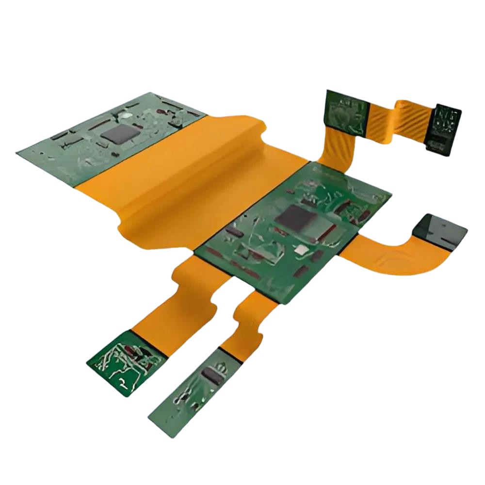
Core Capabilities of Our Rigid-Flex PCB Manufacturer Facility
| Feature / Category | Standard Capability | Advanced Capability |
|---|---|---|
| Layer Count | Flex: 1-6L | Rigid-Flex: 2-20L | Flex: Up to 10L | Rigid-Flex: Up to 30L |
| Finished Thickness | Flex: 0.05 - 0.5mm | Rigid: 0.3 - 3.0mm | Flex: Up to 0.8mm | Rigid: Up to 4.0mm |
| FPC Core (Adhesiveless) | Panasonic (RF-775/777), DuPont (AP) | Taiflex, ThinFlex (1-4mil PI / 0.33-2oz Cu) |
| FPC Core (Adhesive) | Shengyi (SF302 / SF305) | High-flex cycle applications |
| Rigid Base Materials | High-Tg FR4, Halogen-Free | Rogers (RO4000), Arlon (85N), Nelco (N4000-13), Ventec (VT-901) |
| Lamination Prepreg | Standard Flow Prepreg | Low/No-Flow PP (TUC EM-37B, Ventec VT-47N) |
| Drilling Capabilities | Min. Mech Hole: 0.3mm | Min. Laser Microvia: 0.1mm |
| Impedance Control | ±10% (Single/Differential) | ±8% (Down to ±3Ω for ≤50Ω signals) |
| Min. Trace / Space | 3mil / 3mil (0.075mm) | Evaluation required for denser routing |
| ZIF Finger Tolerance | Width: ±0.1mm | Width: ±0.05mm (Precision Fit) |
| Coverlay / Solder Mask | Yellow, Black, White Coverlay | Min Solder Dam: 4mil (Green), 8mil (Other) |
| Surface Finish | ENIG, OSP, Lead-Free HASL | Immersion Silver/Tin, Hard Gold, ENIG + Gold Fingers |
Engineering Reliability: How We Mitigate Manufacturing Risks
Adhesiveless Polyimide Construction
Traditional adhesive-based flex often suffers from desmear issues and delamination during Lead-Free Reflow. We standardize on Adhesiveless PI to ensure a wider thermal processing window and ultimate reliability.
Transition Zone Squeeze-out Control
The interface between rigid and flex is the point of failure. We utilize specialized No-flow Prepregs and conformal release films during vacuum lamination to prevent acrylic adhesive or resin squeeze-out, eliminating trace fracturing risks.
Dynamic Flex Lifecycle Assurance
If your design requires >100,000 bend cycles (e.g., hinges, medical probes). We utilize 1/3 oz or 1/2 oz RA Copper and perform in-house bend cycle testing (up to 1,000,000 cycles) per IPC-6013 standards, ensuring <10% resistance increase.
Impedance & Signal Integrity
Flexible circuits face Dk (Dielectric Constant) variations due to coverlays. We implement hatched ground planes and perform strict TDR testing to guarantee your high-speed signals remain within the ±10% tolerance spec.
Product Configurations: Choose Your Structure
Rigid-Flex PCBs
Combines the best of both worlds. The flex layers are integrated into the rigid layers during lamination.
- Best for: Eliminating connectors, reducing weight, improving signal integrity (no solder joints).
- Key Tech: Bookbinder Construction (staggered lengths) to prevent buckling in high-layer flex sections.
- Final Lamination: Bonding rigid and flex sections together (critical temperature/pressure control).
Multi-Layer Flex Circuits
3 to 8 layers of flexible circuitry connected by plated through-holes (PTH).
- Best for: Complex routing in ultra-compact spaces where rigid boards cannot fit.
- Challenge: Lower flexibility than single-sided.
- Solution: We use Bonded Stiffeners only where components are placed, keeping the rest flexible.
Double-Sided Flex (PTH)
Two copper layers with plated through-holes.
- Best for: General interconnects requiring crossover routing or impedance control (Ground plane + Signal).
- Design Rule: We use Hatched Ground Planes instead of solid copper to maximize flexibility.
Single-Sided Flex
The most basic and flexible structure.
- Best for: Dynamic hinge applications
- Life Cycle: Can achieve millions of flex cycles if designed correctly with 1oz rolled annealed (RA) copper.
Quality Control & Testing
We do not rely on visual inspection alone. For Automotive and Medical sectors, verification is mandatory.
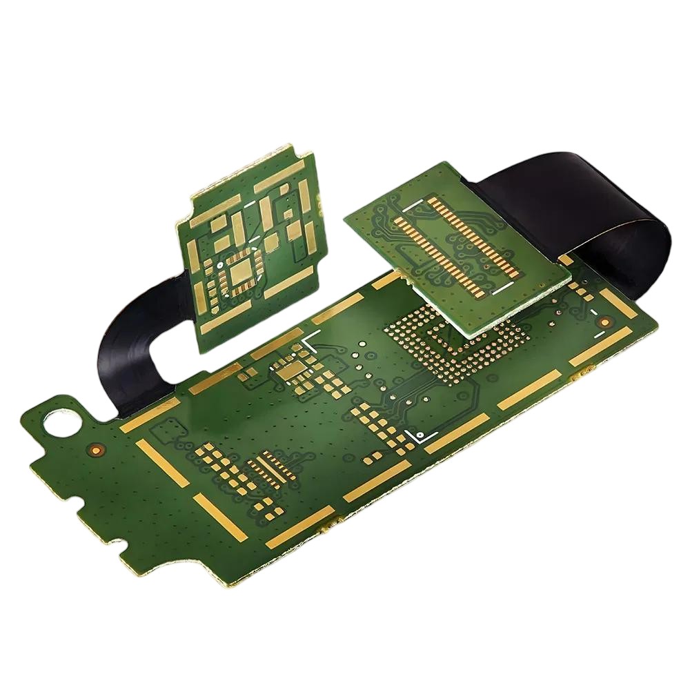
Zero-Defect Approach
Flying Probe for prototypes, Bed of Nails for mass production. Open/Short verification.
First Article Inspection includes detailed cross-sectioning to verify plating thickness, annular ring integrity, and lamination quality in the rigid-flex transition zone.
100% coverage on all inner/outer layers before lamination.
Available for medical and high-voltage industrial applications.
Applications We Support
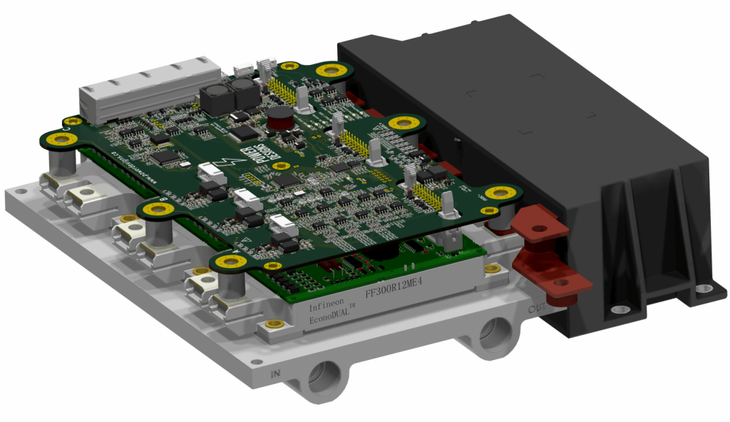
- Engine Control Units (ECU): 8-10 layer boards with -40°C to +125°C operating range
- ADAS Systems: 12-layer designs with controlled impedance for camera and radar modules
- Battery Management Systems (BMS): Heavy copper power planes (up to 18oz) combined with signal layers
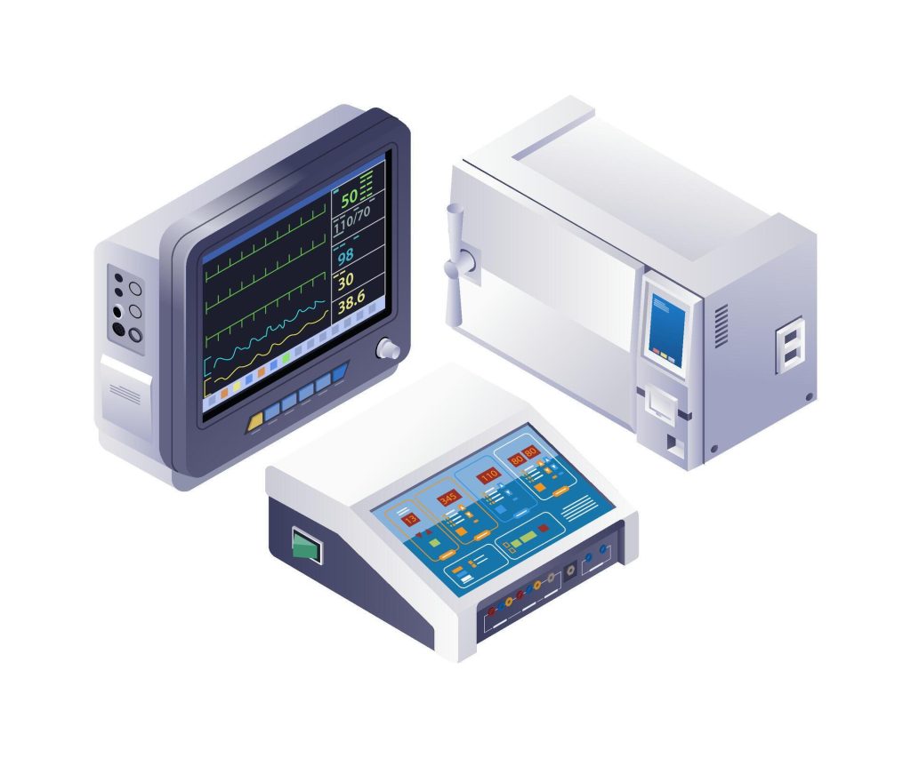
- Patient Monitoring: 6-8 layer boards with low-noise ground planes
- Diagnostic Equipment: 10-14 layer designs for high-speed data acquisition
- Implantable Devices: Rigid-flex multilayer integration for miniaturization
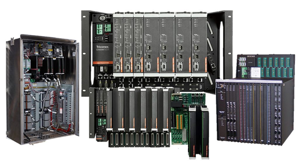
- PLC Controllers: 6-8 layer boards with robust EMI shielding
- Motor Drives: 8-10 layer power boards with 3-6oz copper
- Instrumentation: 10-12 layer precision analog designs with separate analog/digital ground planes
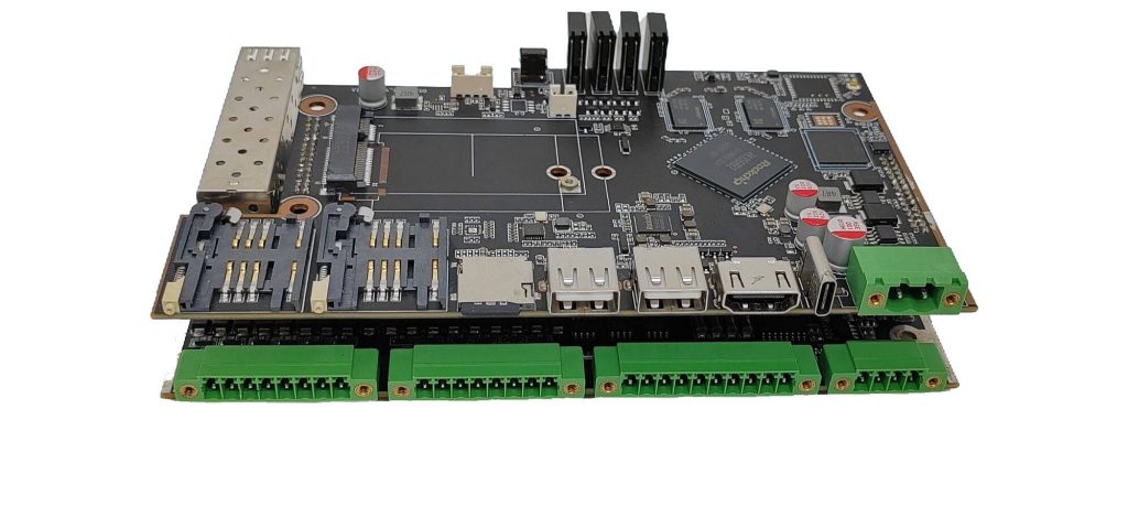
- 5G Base Stations: 12-16 layer RF boards with Rogers 4350B + FR4 hybrid stack-ups
- Gateway Devices: 6-8 layer designs balancing cost and performance
- Smart Sensors: 4-6 layer compact designs with integrated antennas
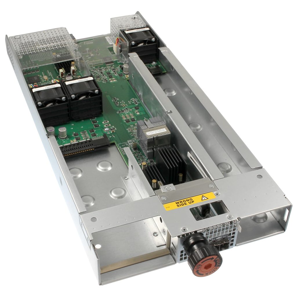
- Avionics: 20-40 layer high-reliability boards with ceramic substrates
- Satellite Communication: 12-20 layer boards with polyimide materials
- Navigation Systems: 10-16 layer precision designs with tight impedance control
Frequently Asked Questions
How do you prevent trace fracturing at the rigid-to-flex transition zone?
We enforce three hard DFM rules at the interface:
No-flow prepregs only, to prevent resin bleed.
A strict 2.0mm via keep-out zone from the bend line to eliminate stress concentrators.
Mandatory teardrops on all pads to prevent copper peeling.
Rigid-Flex is expensive. How do you optimize the Total Cost of Ownership (TCO)?
We cut costs at the CAM stage. First, we aggressively nest panels to maximize DuPont material yield. Second, we recommend “Air-gap” (unbonded) layers for multi-layer flex. This improves flexibility and eliminates the need for redundant, costly stiffeners.
Will the flex layers survive multiple Lead-Free reflow cycles without delaminating?
Yes. Adhesive-based flex bubbles at 260°C, so we default to Adhesiveless Polyimide. It handles high-temp reflows effortlessly. For high-reliability boards, we enforce a strict pre-bake SOP to drive out moisture and verify with microsections. Zero delamination.
Start Your Project with a Trusted Rigid-Flex PCB Manufacturer
Whether it’s a 4-layer prototype or a 40-layer production run, our engineering team is ready to provide free DFM feedback within hours.