
Metal Core PCB Manufacturer
As a leading Metal Core PCB Manufacturer, PCBLion provides high-quality MCPCBs (single/double/multi-layer) with significantly better heat dissipation than standard FR4. Ideal for high-power LED, power electronics, and automotive applications, we offer custom thermal solutions, competitive pricing, and fast delivery.
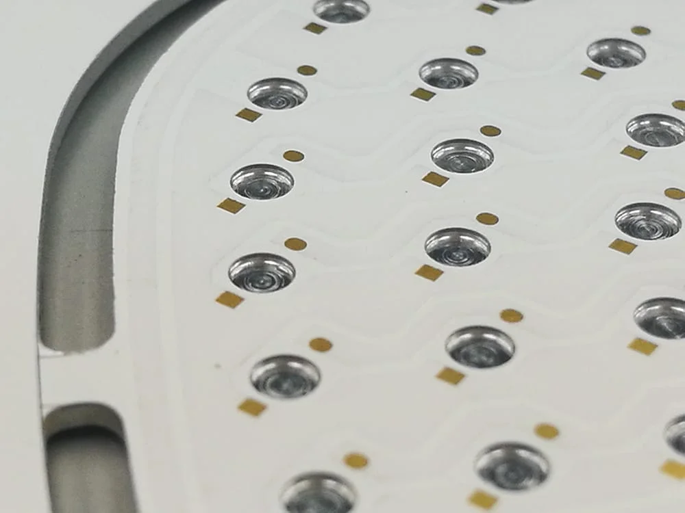
What is MCPCB(Metal Core PCB)?
MCPCBs are PCBs that have a metal core, usually made of aluminum and copper alloy, instead of the traditional FR4 PCB. The metal core PCB has better thermal conductivity and more efficient heat dissipation. As a result, aluminum PCBs is ideal for high-power applications such as swimming pool LED lighting, power electronics, and LED car lighting and hotel lighting.
Single-layer metal core PCB
Single-layer metal core PCB is the simplest MCPCB, which is only composed of a copper layer as the circuit trace, a thermal conductivity layer and a metal base
Two-layer metal core PCB
Two-layer MCPCB means it has two layers circuit layer on this board. But different with double-sided MCPCB, both two layers copper traces are on the same side and metal base located on the bottom side of circuit board.
Double-sided Metal core PCB
The structure of double-sided metal core PCB is the same as normal double sided FR4 circuit board. The metal core is in the middle of the MCPCB and sandwiched by the two layers copper traces.
Multilayer Metal Core PCB
Compared to standard FR4 PCBs, the construction of multilayer MCPCBs requires advanced technology and expertise in laminating multiple layers together with a metal core. As a result, the cost of multilayer MCPCBs is significantly higher than that of 2-layer or double-sided MCPCBs.
Capabilities of Our Metal Core PCB Manufacturer Facility
| Feature / Category | Specification / DFM Rules |
|---|---|
| Substrate Materials | Aluminum (1100/5052/6061), Copper (C1100), Stainless Steel, Iron Alloy |
| Laminate Brands | Shengyi, Quanbao, Xintianyuan, Bergquist & Polytronics (Upon request) |
| Board Structure | Single-Sided, Double-Sided, Multilayer, Thermo-Electric Separation (DTP) |
| Thermal Conductivity | Standard FR4 Prepreg |
| Dielectric Thickness | 50μm, 75μm, 100μm, 125μm, 150μm (Optimized for thermal transfer) |
| Metal Base Thickness | 0.4mm – 3.2mm |
| Copper Weight | 1/3oz to 6oz Standard |
| Max Panel Size | 22.5″ × 30″ (571mm × 762mm) |
| PTH Drill Rules (Based on Base Thickness) | Base < 0.8mm: 0.8mm–6.0mm PTH<br>Base 0.8-1.6mm: 1.0mm–8.0mm PTH<br>Base 1.7-3.2mm: 1.2mm–8.0mm PTH |
| Countersink Holes | Vertical Angle: 90° ± 5° |
| Counterbore Holes | Angle: 30° to 180° |
Substrate Options: Aluminum vs. Copper Core PCBs
Selecting the right metal base depends entirely on your power density and budget constraints. We stock and process both primary types:
The industry standard for cost-effective heat dissipation. Highly recommended for standard LED lighting, audio equipment, and consumer power converters.
Heavier and more expensive, but offers double the thermal transfer rate. Required for extreme power densities, such as Electric Vehicle (EV) power modules, high-frequency RF amplifiers, and heavy-duty rectifiers.

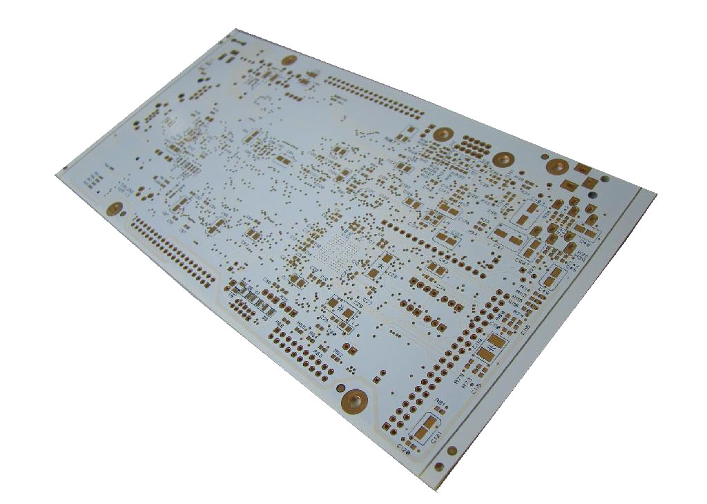
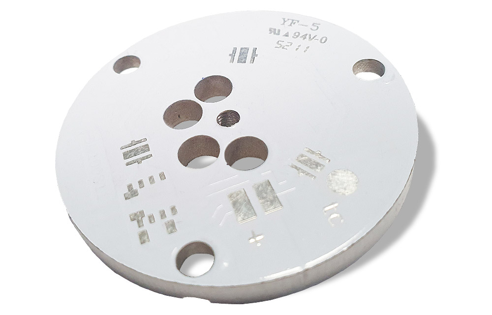
Controlling the Thermal Bottleneck
Manufacturing MCPCBs requires entirely different tooling and process controls compared to rigid FR4. Here is how PCBLion prevents common field failures:
In power electronics, the metal base poses a severe short-circuit risk if the thin dielectric layer (typically 100μm - 200μm) breaks down. We rigorously control lamination pressure and perform mandatory Hi-Pot (High Potential) testing at >3000V on every batch to guarantee electrical isolation and operator safety.
For extreme localized heat (e.g., automotive laser headlights), even an 8W/m·K dielectric layer acts as a barrier. We manufacture Thermo-electric Separation (DTP) boards, where the thermal pad of the component is soldered directly to a raised copper boss (pedestal) on the base metal. This achieves an effective thermal conductivity of >100 W/m·K.
Routing solid aluminum or copper quickly wears down CNC drill bits, often leaving microscopic metal burrs that can pierce the dielectric layer and cause lethal shorts. We utilize specialized routing bits and strict tool-life management to ensure perfectly smooth, burr-free edges and precise Countersink holes for flush heatsink mounting.
The PCBLion MCPCB Advantage
With 18 years of dedicated experience and a 25,000 m² facility, we scale thermal management solutions from prototype to mass production for 500+ global innovators.
Solid metal cores provide exceptional thermal conductivity (up to 8W/m·K), rapidly moving heat away from high-power LEDs and EV power electronics.
Eliminates the need for bulky external heat sinks. Achieves higher component density in space-constrained designs without thermal throttling.
Aluminum and copper bases are highly recyclable, reducing your product's carbon footprint while strictly adhering to global RoHS and REACH standards.
Delivers extreme thermal management approaching expensive ceramic PCBs, but at a fraction of the cost. Optimized for volume manufacturing.
Why Engineers Switch to Us
“PCBLion’s Direct Thermal Path (DTP) technology on our copper-core boards reduced our LED junction temperature by 15°C. Their engineering support and mass production consistency are unmatched.”
— Hardware Lead, Automotive Lighting Systems
Applications We Support
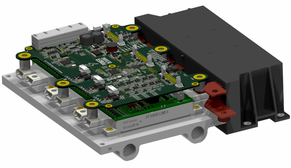
- Engine Control Units (ECU): 8-10 layer boards with -40°C to +125°C operating range
- ADAS Systems: 12-layer designs with controlled impedance for camera and radar modules
- Battery Management Systems (BMS): Heavy copper power planes (up to 18oz) combined with signal layers
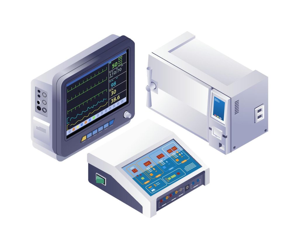
- Patient Monitoring: 6-8 layer boards with low-noise ground planes
- Diagnostic Equipment: 10-14 layer designs for high-speed data acquisition
- Implantable Devices: Rigid-flex multilayer integration for miniaturization
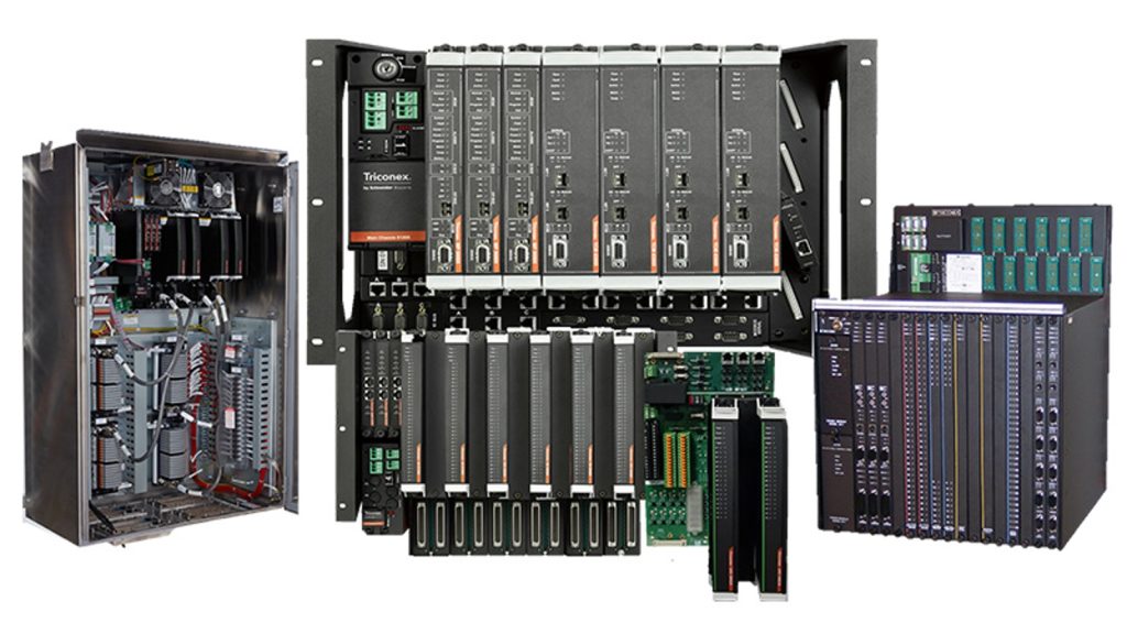
- PLC Controllers: 6-8 layer boards with robust EMI shielding
- Motor Drives: 8-10 layer power boards with 3-6oz copper
- Instrumentation: 10-12 layer precision analog designs with separate analog/digital ground planes
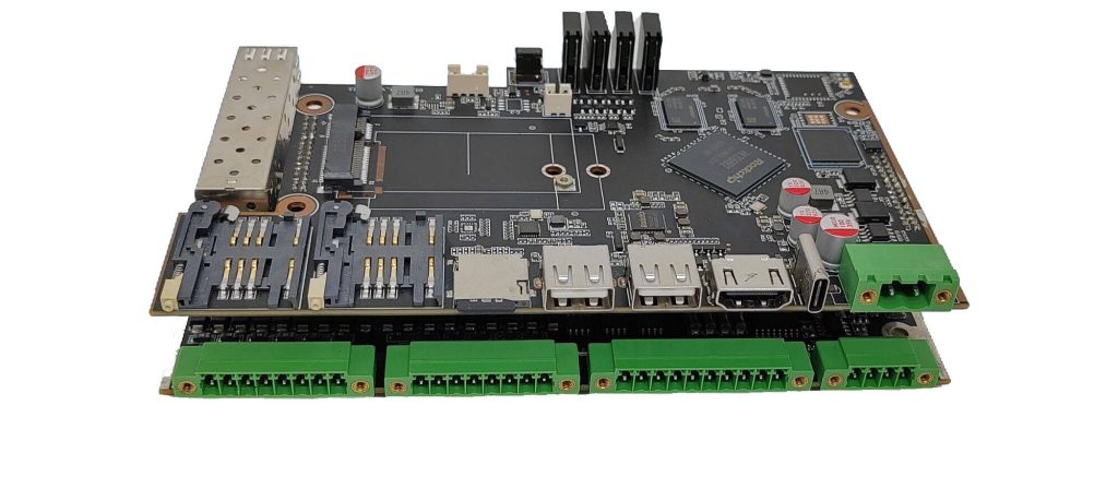
- 5G Base Stations: 12-16 layer RF boards with Rogers 4350B + FR4 hybrid stack-ups
- Gateway Devices: 6-8 layer designs balancing cost and performance
- Smart Sensors: 4-6 layer compact designs with integrated antennas
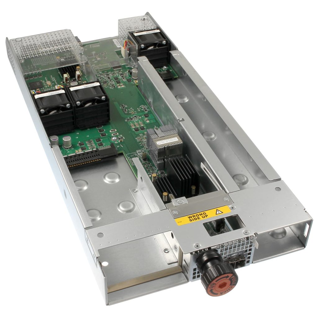
- Avionics: 20-40 layer high-reliability boards with ceramic substrates
- Satellite Communication: 12-20 layer boards with polyimide materials
- Navigation Systems: 10-16 layer precision designs with tight impedance control
Frequently Asked Questions
Can you manufacture double-sided or multilayer MCPCBs with plated through-holes (PTH)?
Yes. For double-sided or multilayer metal core boards, we must pre-drill oversized holes into the metal base, fill them with insulating epoxy resin, and then re-drill and plate the vias. This ensures the via connects the copper signal layers without short-circuiting to the solid metal core.
How does copper weight affect the minimum trace and space on a metal core board?
Thicker copper requires wider spacing to account for chemical etching tolerances. For example, a standard 1oz copper layer can support 4mil/4mil spacing. However, a heavy 4oz copper layer on an MCPCB will require a minimum of 8mil/8mil spacing to prevent shorts. Our CAM engineers verify this during DFM.
What is the difference between FR4 with thermal vias and an MCPCB?
Standard FR4 relies on arrays of plated thermal vias to move heat through the fiberglass. It is cheaper but limited in capacity. An MCPCB replaces the fiberglass entirely with solid metal, providing a massive, unbroken thermal highway. If your design requires dozens of thermal vias to survive, it is time to switch to an MCPCB.
Ready to Start Your Project with a Trusted Metal Core PCB Manufacturer?
Get an instant quote and see why thousands of engineers trust PCBLion for their PCB needs.